© 2004, 2005, 2006, 2007 by Man of the Cloth Productions
Since the Zephyr was constructed with walls that “sandwich” a frame between two skins of plywood, I planned the placement of the electrical wiring in each step of building the teardrop. For example, when I built the first wall I used the router to cut grooves in the frame for the wires that energized the clearance lights at the front point of the trailer.

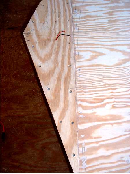
Here is a close up of the groove I cut into the frame for the wiring. I used a red and black wire for each wiring circuit.
![]()
This photo shows where the clearance light wires came through the wall to the outside.
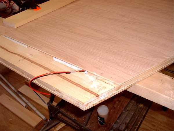
I made another cut with the router at the bottom of the wall. When the wall was fastened to the deck, I passed the wiring through the band board on the side of the deck. Later on, I spliced this circuit into the trailer wiring harness to energize this circuit.
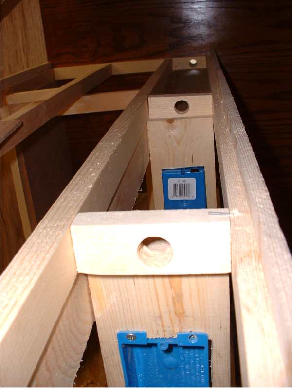
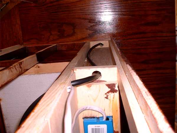
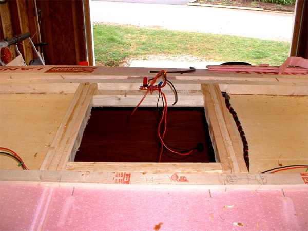
When I built the bulkhead, I included an electrical chase. This space allowed me to pass the wires that needed to pass from one point to another. The photo below, shows where I placed holes in the horizontal chase for the AC line from outside.
I installed two AC outlets inside the cabin area as seen in the photo. The horizontal chase was located between these outlets. I left the bottom of the vertical chase open for ventilation and access.
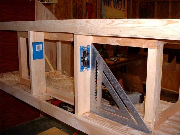
I used 14/2 round woven wire (black, white, ground) for the line carrying AC load from outside. Interior AC wire in the photo was 14/2 Romex.
Using the router, I cut a recess into the wall at a location reinforced by the internal frame. The Zephyr has a 15 amp circuit breaker to limit the current in the camper’s system. The plug I used to connect to shore power was also rated for 15 amps.
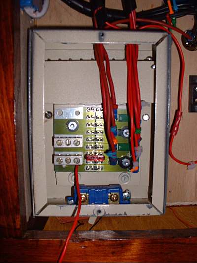
When the back of the galley was finished, I installed a "Square D" load box with one 15 amp circuit breaker. The black wire pictured above energized this breaker box. I used 14/2 household Romex to wire the rest of the circuit. (The circuit could be wired with 12/2 to power higher amperage appliances.) I ran the circuit from breaker box to a ground fault interrupt (GFI) outlet in the galley. Following the GFI directions, I wired the cabin outlets from the load side of the GFI. With this set up, all outlets are protected by the GFI and by the breaker. I wanted GFI protection because of the wet environment of camping in bad weather.
Note: A circuit breaker is not made to be used as a switch. Manufacturer’s instructions state "Breakers should be tested monthly". But repeated use of a breaker as a switch will cause them to wear out.
This photo, taken from inside the cabin, shows the 14/2 Romex in the vertical chase.
The line at the top came from the circuit breaker and energized the line side of the GFI. The Romex going to the outlet on the right, came from the load side of the GFI. The Romex at the bottom continues the circuit. I always remembered this: "Black wire to gold screw, white wire to silver screw, ground wire to ground screw (green)." The hole in the panel was for a DC outlet to the galley I installed later.
My next
step in installing an electrical system was the DC system.
I ran all the wires for the cabin in the space above the ceiling skin. I drilled holes in the spars so I could pass the wires through. It looked like wire spaghetti, so I marked each pair of wires with a uniquely colored wire tie.
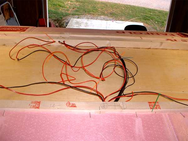
I used 12
gauge woven wire for durability, since these wires will be inaccessible
after the roof is attached. I did not use the trailer frame as the return
for any circuits. I gave each DC load its own red and a black
wire for a circuit. This was a little more costly, but I wanted the added
reliability of the heavier wire circuits.
I added the framing for the roof vent at this time. As I insulated the ceiling I finalized the layout of the wires.
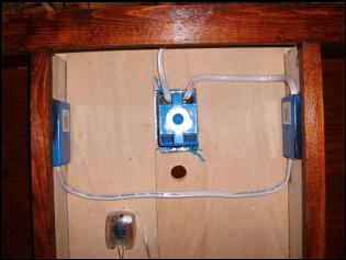
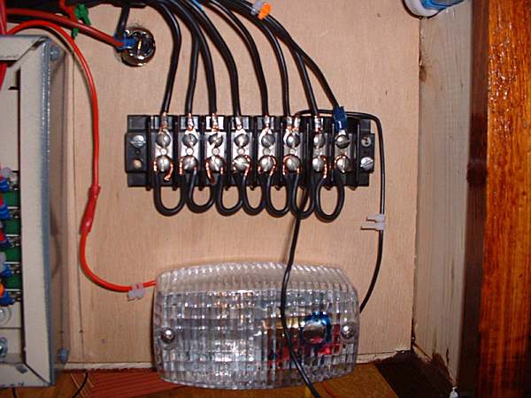
The photo below, shows a step when I wired all the + DC
loads to the fuse panel. In this test, I energized a circuit with the small
temporary wire at the lower left. Only one circuit had a fuse installed in
the photo. To complete the
installation I used an automotive fuse to protect each circuit. I identified the wires of each circuit with a colored wire
tie. For safety I closed the fuse box with a lid.
In this picture I
connected a temporary test wire to the bottom right of the terminal bar.
After the test, I connected all the - DC return lines to screws on the
terminal bar. The wire looped at the bottom of the bar tied all these
returns together electrically. Then I connected the main - return to the
bottom of the terminal bar. I
covered the terminal bar with an insulated plate for safety.
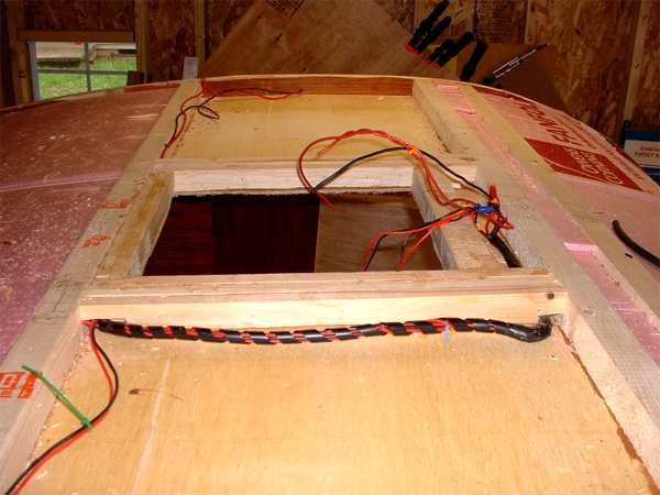
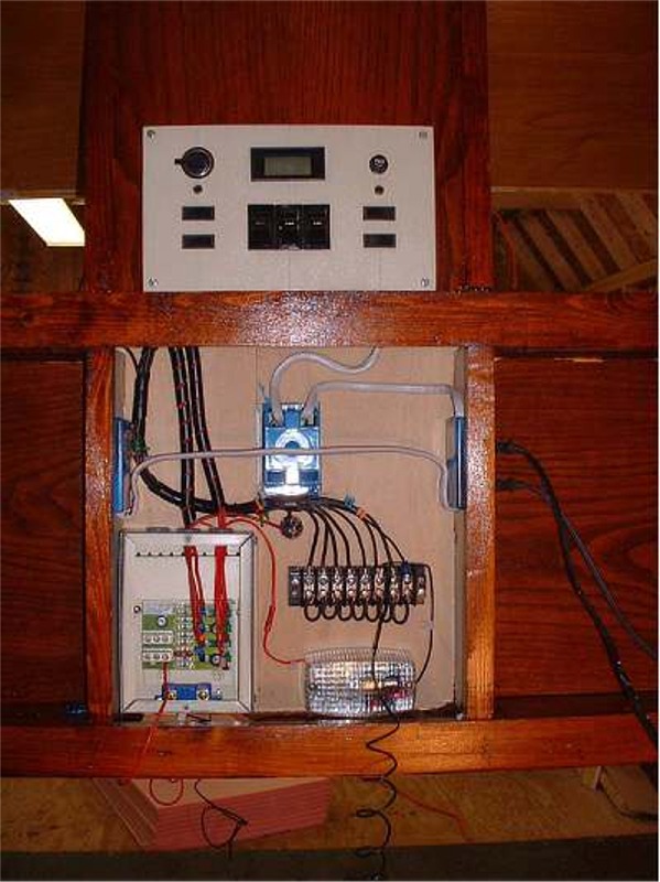
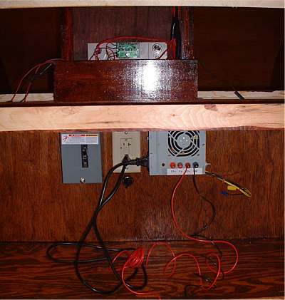
Here is what the horizontal electrical chase looked like near completion.
This photo includes labels of the circuits after they were connected to the control panel.
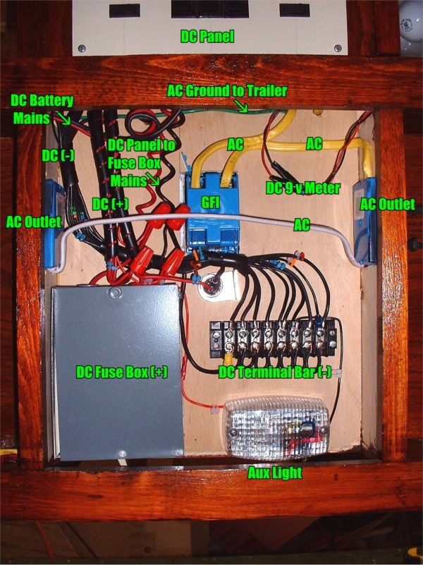
The main + DC line came from the battery or the AC-DC converter into the main control panel. These main lines were 10 gauge. I connected the main + DC line (red) to a SPDT switch in the control panel. I connected the main - DC return (black) to another SPDT in the control panel. I used SPDT switches so I could select from the control panel which DC power source I wanted to use to energize the DC circuits: either the converter or the batteries. I connected the main + line (red helix) from the panel switch to the "master kill" switch at the bottom of the fuse box. I connected the main return - (black helix) from the black terminal bar to the other panel switch.
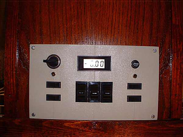
I
installed the control panel at the top of the electrical chase. The
switches I located in the center are used to select the source of DC power
(battery or AC-DC converter) and to control the meter. The fuse in the
panel protects the meter. The side switches control the fan and the porch
lights. The meter shows the state of charge in the 12 volt battery.
I mounted the AC to 12 volt DC converter in the galley. The converter was plugged into and protected by the GFI circuit. This switching power supply has a built-in interrupt. If the AC-DC converter grounds without a load, it shuts off on its own.
This graphic shows the Zephyr's electrical system in schematic form.
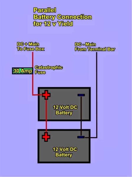
When I am away from AC shore power the DC system is powered by two gel batteries. The reason I started with these was that they were given to me. I wired them in parallel (red to red and black to black). This keeps the voltage at 12 v DC and yields about 75 amp hours. This should be enough for a weekend and probably a few more days of careful use. All wires from the batteries to the switch panel were 10 gauge woven wire automotive wire. I used soldered terminal lugs for l these battery harness connections. The terminal lugs were connected to the terminal posts with bolts. I added protective plastic wire loom to guard against friction chaffing.
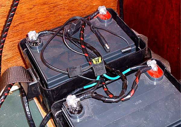
I placed a 30 amp fuse in the main DC + line that energized the DC fuse box. This is installed as close to the battery as possible. Its purpose is to protect the electrical system in the event of a sudden catastrophic drainage of amperage.
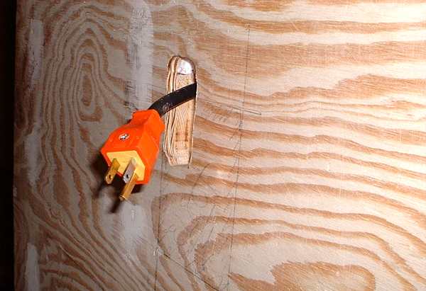
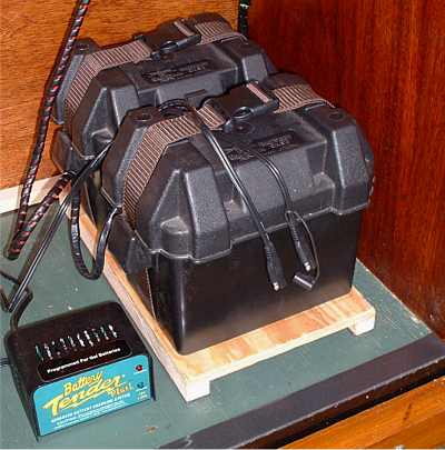
I also installed a quick connect terminal so I can charge the batteries even when they are inside the battery cases. I purchased a battery tender that was designed specifically for charging gel batteries. The picture below shows the quick connect plugs that I use to connect the charger. Sealed gel batteries don't vent gasses like lead acid batteries do when charging. I bolted the battery cases to the wooden frame. I also applied neoprene weather stripping to the bottom of the frame so the battery rack doesn't slide around. In the final installation, I will make sure the batteries can't tip over.
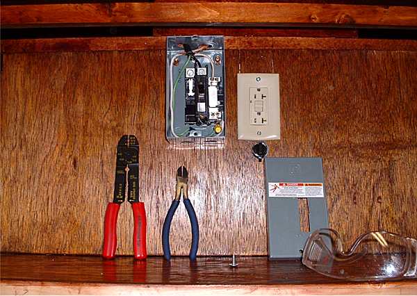
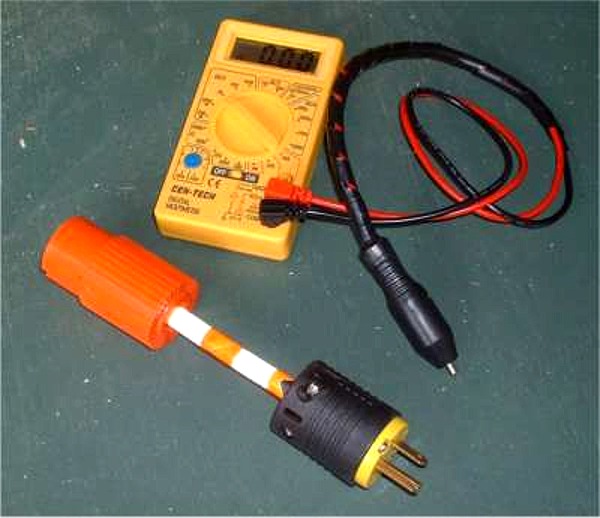
I made two other devices for the safe operation of my electrical system. I used one to monitor the battery through the DC circuits in the Zephyr. I used the other to correct an occasional problem with AC shore power connections.
The first device is pictured below at the top of the photo. I attached a 12 volt DC plug to the end of a set of spare leads for a multimeter. I was careful to match the polarity of the plug to the polarity of the DC outlets in the Zephyr. If this was reversed, then the meter would read negative voltage. I plugged this into any 12 volt outlet in the Zephyr to read the state-of-charge in the battery.
In some campgrounds, the line and the load side of the AC circuit are mistakenly reversed in the shore power outlets. This condition isn't safe, even though a simple device, like a light, will work if plugged into such an outlet. Other electronic devices, like my AC-DC power converter and battery charger, will not work and can be damaged if plugged into an outlet that is wired incorrectly.
To guard against this, I bought a simple plug-in polarity tester. With the tester, I could verify correct polarity in the AC shore power outlets at campgrounds. The pattern and color of the LED display on the plug-in tester indicated correct polarity and a safe outlet or reverse polarity. I made the device shown in the bottom of the above photo to use when the tester showed the polarity was reversed. It consisted of female and male three-prong, grounded plugs connected via six inches of suitable wire. I purposefully switched the line/load polarity in this plug. I made sure that the continuity of the grounded leg (green wire) remained. When I found reversed polarity in the shore power outlet at a campsite, I plugged in my adapter at the shore power location. The adaptor switched the AC current back to the correct polarity. It was a temporary fix and I used it with care. I made it very short and marked it with unmistakable colors. I did this so I wouldn't use it by mistake when not needed and cause a dangerous problem.
.Please visit this sponsor